
Before starting leakage tests like hydrostatic testing or pneumatic testing, piping network and connected equipments must be prepared for leakage tests. ASME B31.3 provides guidelines for such preparation.
Piping which is normally open to the atmosphere, such as drains, vents, discharge piping from pressure relieving devices, sewers, and stack downstream of the seal drum, shall not be subjected to the piping test pressure.
Compare PID and Isometric Drawing
 A comparison of the P&ID drawings and the piping isometrics must be made to determine if there are any discrepancies. Review all valve types, flow directions, branch tie-ins, and any material changes. Recheck all in-line components to verify they can withstand the required test pressure.
Complete Inspection before testing
 All radiographic and ultrasonic inspections should be carried out before the pressure test is started. Conducting 100% radiography of all the weld joints assure that your weld joints are defect free but can never provide you with the assurance of mechanical integrity of a system. This is also to be noted that radiography / ultrasonic inspection shall also not to be waived off if the pipeline is to be hydrostatically tested.
Joints shall be exposed
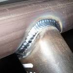 As per ASME B31.3 Section 345.3.1 all joints, welds (including structural attachmentwelds to pressure-containing components), and bonds shall be left uninsulated and exposed for examination during leak testing, except that joints previously tested in accordance with this Code may be insulated or covered.
All joints may be primed and painted prior to leak testing unless a sensitive leak test (para. 345.8) is required.
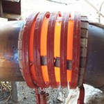
Provision of Temporary Supports
 As per ASME B31.3 Section 345.3.2 piping designed for vapor or gas shall be provided with additional temporary supports, if necessary, to support the weight of test liquid as the test liquid is heavier than service gas.
Spring Supports in Piping System
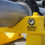
 Spring supports shall be restrained or removed during hydrostatic testing. Piping which is spring or counterweight supported shall be blocked up temporarily to a degree sufficient to sustain the weight of the test medium. Holding pins shall not be removed from spring supports until testing is completed and the system is drained. Care shall be taken to avoid overloading any parts of the supporting structures during hydrostatic testing.
Piping with Expansion Joints
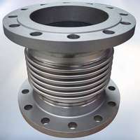 As per ASME B31.3 Section, when there is an expansion joint in piping system under leakage test, following criteria applies.
(a) An expansion joint that depends on external main anchors to restrain pressure end load shall be tested in place in the piping system.
(b) A self-restrained expansion joint previously shoptested
by the manufacturer [see Appendix X, para. X302.2.3(a)] may be excluded from the system under test, except that such expansion joints shall be installed in the system when a sensitive leak test in accordance with para. 345.8 is required.
(c) A piping system containing expansion joints shall be leak tested without temporary joint or anchor restraint at the lesser of
(1) 150 % of design pressure for a bellows-type expansion joint, or
(2) the system test pressure determined in accordance with para. 345
In no case shall a bellows-type expansion joint be subjected to a test pressure greater than the manufacturer’s test pressure.
(d) When a system leak test at a pressure greater than the minimum test pressure specified in (c), or greater than 150% of the design pressure within the limitations of para. 345.2.1(a) is required, bellows-type expansion joints shall be removed from the piping systemor temporary restraints shall be added to limit main anchor loads if necessary.
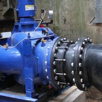
Limits of Tested Piping
As per ASME B31.3 Section 345.3.4 equipment which is not to be tested shall be either disconnected from the piping or isolated by blinds or other means during the test. A valve may be used provided the valve (including its closure mechanism) is suitable for the test pressure.
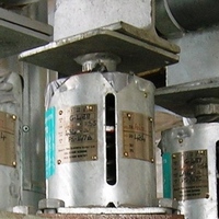
Rotary Machinery
 For rotating machinery, such as pumps, turbines, and compressors., have lube and seal oil systems which could be impaired by the presence of water. These systems shall not be subjected to the piping test pressure.
Temporary Spades and Blanks
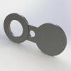 Temporary spades and blanks installed for testing purposes shall be designed to withstand the test pressure without distortion. Presence of spades shall be clearly visible during testing. The recommended practice is to use standard blind flanges as per ASME B16.5 or B16.47 and spades acc. to ASME B16.48.
Check Valves
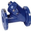 Check Valves shall have the flap or piston removed for testing, where pressure can not be located on the upstream side of the valve. The locking device of the flap pivot pin shall be reinstated together with the flap and a new cover gasket shall be installed after completion of the test.
Completion of Hot Work
 Hydrostatic test has to be performed after all hot works have been completed on a certain piping system. Hot work includes everything related to welding or the post weld heat treatment (PWHT).
Installation of Barriers
 Prior to any pressurization related to testing, it is essential to install barriers around piping system under test. Public Address announcements are also to be made and access restriction procedures such as permit to work are implemented. Under no circumstances should anyone other than an authorized person be allowed within the safety barriers.
Control Valves
 Control Valves and soft-seal block Valves shall be removed from the piping prior to the test and replaced with pipe spools.
Physical Inspection
Check for following :
- Completed and torqued flanges with no missing bolts or gaskets.
- All gravity supports installed.
- Proper pipe routing.
- Correct valve type and orientation.
- Vents and drains installed to allow proper filling and draining
- Proper material type verified using color codes or markings, and heat numbers recorded if required by the codes.
- All required piping stress relief, weld examinations, and welding documentation completed and acceptable.
Testing Documentation
The individual system documentation i.e. test pack shall be available prior to any testing and shall include information such as test limits, test pressure, test medium, duration, test blinds, blind flanges, vents and drains.
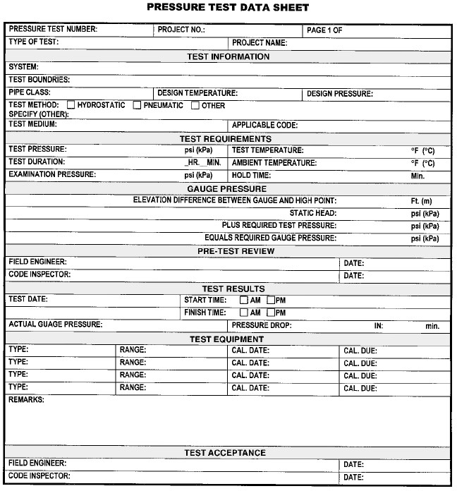
The use of marked up P&Ids coupled with isolation registers should be utilised to identify the locations of blinds, Valves, vents and drains.
Testing Equipment
 Testing equipment such as pumps, manifold, pressure and temperature recorders, pressure gauges should be within calibration/certification (as per company procedures) and connected to the lowest convenient connection within the system to ensure best results.